- This topic is empty.
-
AuthorPosts
-
2026-10-14 at 1:37 pm #14709
Choosing a Hall-effect current sensor means fixing six things in order: what current type you measure (AC, DC or pulsed), the current range including peaks and overload, the conductor arrangement (through-hole, split-core, busbar, cable or modular), whether galvanic isolation is required, the supply and output signal your controller expects, and the accuracy/response demands of the application. KJT Sensors’ current-sensing line covers Hall-effect, fluxgate and shunt-resistor principles across ranges from milliamperes to kiloamperes, with live product series in open-loop, high-precision open-loop, closed-loop, high-precision closed-loop configurations plus Hall voltage sensors/transducers and a DC leakage-current sensor (manufacturer-stated; series confirmed on the product pages). Measuring range, opening size, supply and output are confirmed for the specific model.
Key Takeaways
- Current type first: AC, DC or pulsed — it decides the principle and the output behaviour before any range discussion.
- Range includes overload: specify nominal current, peak current and the overload the sensor must survive, not just the steady-state value.
- Isolation is often the reason Hall is chosen at all: galvanic separation between the high-voltage circuit and the control unit, with higher-end KJT models integrating it (manufacturer-stated).
- Open-loop vs closed-loop is a precision/price decision: closed-loop compensation for accuracy and bandwidth; open-loop for compactness and economy — KJT offers both, plus high-precision versions of each.
- mA to kA coverage is a family statement: the exact range, aperture, supply and output are per-model confirmations.
- Noise or offset problems on an installed sensor are a diagnosis case, not a selection redo.
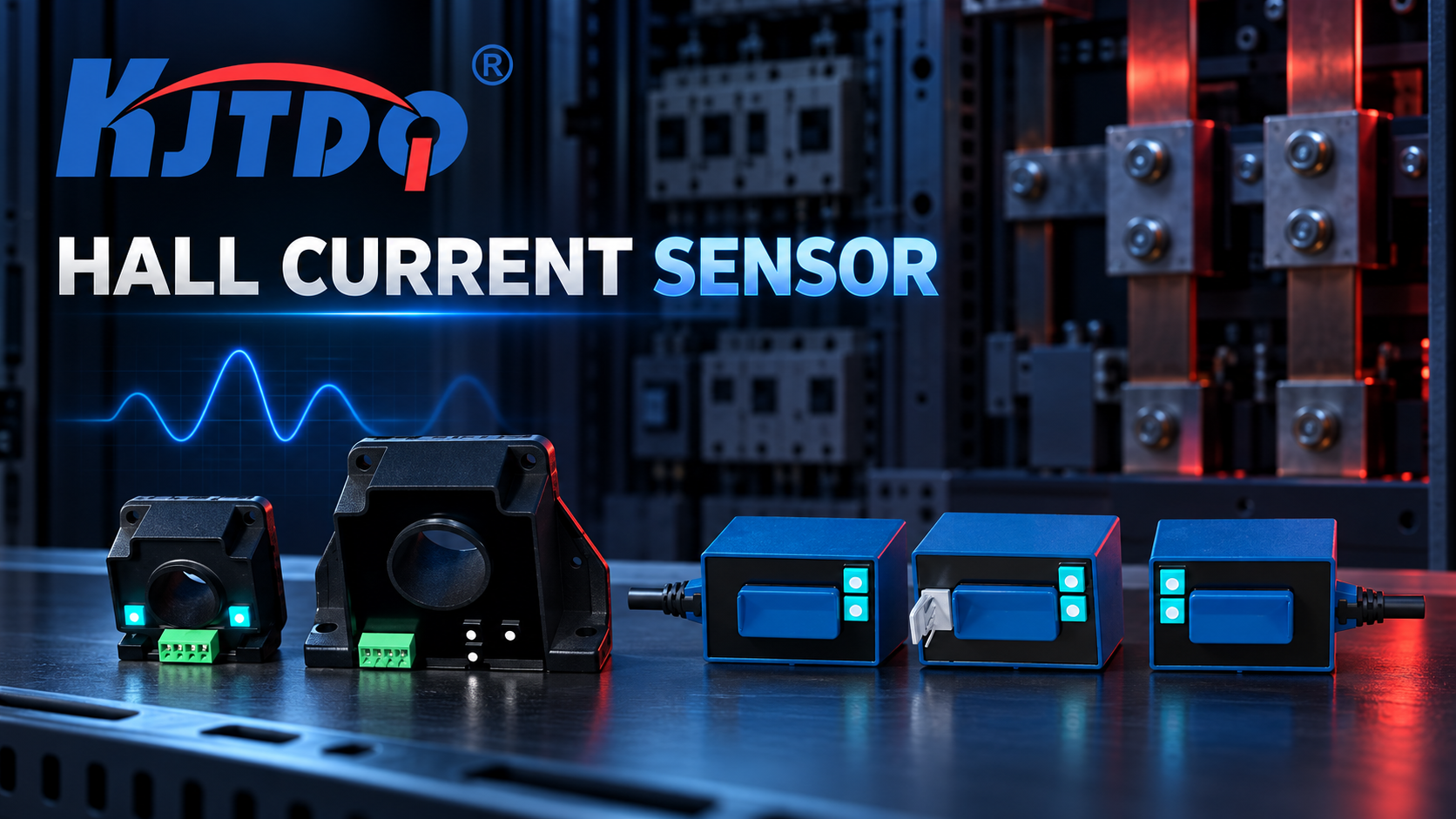
Step One: Define the Current Type
The measured current is AC, DC or pulsed, and the answer flows through everything downstream — KJT’s selection guidance lists it as the first confirmation (manufacturer-stated):
- DC: continuous currents in battery systems, DC distribution, electrolytic loads. Hall-effect (and fluxgate) sensing measures DC directly — unlike current transformers, which are AC-only.
- AC: alternation at power or drive frequencies; range and bandwidth must cover the fundamental plus any harmonics you need to see.
- Pulsed: switching converters, welders, pulsed loads — where peak amplitude, duty cycle and rise time all matter to what the sensor must track.
KJT Sensors’ Hall-effect electrical sensors convert AC, DC or pulse current into a standard voltage or current signal for downstream acquisition, analysis, control and protection (manufacturer-stated).
Step Two: Specify Range, Peaks and Overload
The range specification has three layers:
- Nominal measuring range — the current class the sensor is built for. KJT’s family spans milliamperes to kiloamperes (manufacturer-stated); the model covers one window of it.
- Peak/overload capability — what the sensor must survive beyond nominal (inrush, fault current, startup transients). The selection guidance names overload capability alongside range (manufacturer-stated); the per-model figure decides survival.
- Resolution at the bottom — the smallest current change that matters (leakage detection, standby currents). The DC leakage-current sensor series exists precisely for the low end.
Step Three: Fix the Conductor Arrangement
The sensor must mechanically accept the conductor it measures — KJT’s guidance lists the mounting method explicitly: through-hole, split-core, busbar, cable or modular installation (manufacturer-stated):
Arrangement Typical use Notes Through-hole PCB-mounted primary conductor or busbar Fixed installation; opening size per model Split-core Retrofit around an existing cable without disconnection Installation convenience at some precision cost Busbar Panel/busbar monitoring Mechanical adaptation to bar geometry Cable Cable-pass sensing Opening must fit the cable OD Modular Control-cabinet integration Standardized mounting The opening/aperture size is a per-model figure — a conductor that does not fit, or fits with excessive clearance, changes both mechanics and accuracy.
Step Four: Decide on Isolation
Galvanic isolation between the high-voltage side and the control unit is a safety and system-integrity function: KJT’s documentation states that some higher-end models integrate isolation between high-voltage circuits and control units to improve system safety, and that high-voltage, high-power and rail-transit applications require particular attention to isolation voltage, reliability, response time and safety requirements (manufacturer-stated). For low-voltage sensing the requirement may be relaxed; for anything at power-potential, isolation voltage is a headline specification confirmed per model.
Step Five: Match Supply and Output
The sensor feeds a controller, so the last mile is electrical compatibility:
- Supply voltage — whatever the model requires; a per-model figure;
- Output signal — standard voltage or current signal (manufacturer-stated), i.e., the analog interface family; the scaling between measured current and output follows the model’s datasheet;
- Controller input — the analog-input discipline (scaling, sampling, resolution) is the same as for any analog sensor; the general interface comparison between 4–20 mA, 0–10 V, RS485 and IO-Link belongs to the interface-selection guide, and sensor-output-to-PLC matching to the integration guide.
Accuracy, response speed and interference immunity — the family’s stated strengths (manufacturer-stated) — are per-model values to check against the application: protection duties need response speed; metering duties need accuracy; both need the EMI environment evaluated.
Hall-Current Application Specification Checklist
The article’s original asset:
# Item Your answer 1 Current type: AC / DC / pulsed 2 Nominal current; peak current; overload to survive 3 Smallest current that must resolve (if any) 4 Conductor arrangement: through-hole / split-core / busbar / cable / modular; conductor size 5 Isolation required? Isolation voltage class 6 Supply voltage available 7 Output required: voltage / current signal; scaling 8 Accuracy and response-speed requirement 9 Environment: temperature, EMI sources (VFDs, motors), vibration 10 Certification / application class (industrial control, new energy, rail, power electronics) KJT Sensors Options
Confirmed live on the product pages (verified 2026-10-10): Open-loop current sensor, High-precision open-loop current sensor, Closed-loop current sensor, High-precision closed-loop current sensor, Hall voltage sensor, Hall voltage transducer, Hall current transducer, and DC leakage current sensor series. The manufacturer’s family-level anchors: Hall-effect, fluxgate and shunt-resistor technical directions; ranges from mA to kA; fast response, high accuracy, strong interference immunity; isolation in higher-end models; applications across power electronics, industrial control, new energy, rail transit, industrial inverters, high-power rectifiers, furnace power supplies and energy management (all manufacturer-stated).
The closed-loop direction is highlighted for interference immunity, high isolation voltage and reliability in high-current applications such as rail-traction systems, large industrial inverters, high-power rectifiers and furnace power supplies (manufacturer-stated). Measuring range, opening size, power supply and output type are confirmed for the specific model. Pricing is quoted by model and project requirements, driven by sensing principle, range, accuracy, isolation level and mounting structure.
Limitations and Validation Needs
- mA-to-kA coverage, response speed and accuracy are family-level manufacturer statements; every numeric value is a per-model confirmation.
- Shunt-resistor and fluxgate alternatives exist within the KJT line — the “Hall-effect” title covers the family’s dominant principle, but the optimal principle for a given application (e.g., fluxgate for precision DC) should be discussed with the supplier.
- Electrical-safety statements (isolation voltage classes) must be read against each model’s certification documents before design commitment — qualified electrical review is mandatory for this article’s wiring and isolation statements.
- Offset drift and noise on an installed sensor have a diagnostic treatment (hall-current-sensor noise diagnosis) distinct from selection.
FAQs
What current range and overload must be measured? Three numbers, not one: the nominal current class (the family spans mA to kA, manufacturer-stated), the peak current the application produces, and the overload the sensor must survive without damage — inrush and fault currents included. All three are per-model confirmations.
Which output and supply are required? The controller defines them: the sensor’s supply voltage per model, and its output — a standard voltage or current signal (manufacturer-stated) — matched to the controller’s analog input and scaling. The wider interface-technology comparison (4–20 mA vs 0–10 V vs RS485 vs IO-Link) is its own guide (interface-selection guide).
Which conductor position and installation-clearance requirements must be verified? The mechanical arrangement — through-hole, split-core, busbar, cable or modular — with the opening size fitting the conductor, and installation clearance around high-voltage conductors per the applicable electrical-safety rules. An aperture that fits tightly or loosely both matter; clearance around the primary conductor is an electrical-safety decision requiring qualified review.
Open-loop or closed-loop? Closed-loop compensation serves accuracy, bandwidth and drift-critical duties — KJT highlights its closed-loop direction for interference immunity, high isolation voltage and reliability in high-current applications (manufacturer-stated). Open-loop serves compactness and economy where those margins are acceptable. KJT offers high-precision variants of both paths.
Why is isolation required at all? Galvanic isolation separates the measured high-voltage circuit from the control unit — protecting people and electronics, and enabling measurement at potentials the control side must not touch. Higher-end KJT models integrate it (manufacturer-stated); the isolation-voltage class is a per-model headline specification for power, rail and traction applications.
Can KJT Sensors customize a Hall current sensor for an OEM system? The line supports OEM discussion — range, aperture, supply, output, isolation, housing and connector are customization dimensions, with sample testing and OEM quantities part of the process. Send the checklist above with quantities; the specification discipline for custom requests is covered in the custom-sensor guide.
Conclusion
Hall-current selection is an electrical specification written in order: current type, range with peaks and overload, conductor arrangement, isolation class, supply and output, then accuracy and response against the duty. KJT Sensors’ series structure — open-loop, high-precision open-loop, closed-loop, high-precision closed-loop, plus voltage/transducer and leakage variants — maps onto that specification cleanly once the six steps are answered. Fix the numbers, confirm the model, and have the wiring and isolation statements reviewed by a qualified electrical engineer.
Sources
- KJT Sensors, Hall Current Sensor product pages (open-loop / closed-loop / high-precision / voltage / transducer / leakage series, verified accessible 2026-10-10): https://www.kjt-sensors.com/list-hall_current_sensor.html
- KJT Sensors, Hall-Effect Electrical and Current Sensor product data (internal knowledge base, Grade B manufacturer-stated)
https://www.kjt-sensors.com/
KJT Sensors -
AuthorPosts

- You must be logged in to reply to this topic.