- This topic is empty.
-
AuthorPosts
-
2026-11-09 at 5:26 pm #15124
DALY BMS | ENGLISH BLOG ARTICLE
Introduction
A battery management system must be matched to the battery pack and connected in accordance with the correct product documentation. The DALY materials supplied for this article include a 16S wiring example and an overview of the main connections. The diagram can help readers recognise the labels used in that example; it is not a complete installation procedure and must not replace the manual for the exact BMS model, board revision and battery pack.
Recognise the terminals in the supplied 16S diagram
The reference diagram labels the battery pack’s main negative and positive terminals as B− and B+. It also identifies BMS-side power connections P− and P+, a C−/P− connection, battery sampling leads and a display connection. These labels describe the illustrated example only. Terminal functions, connector locations and wiring arrangements may differ between BMS variants, so always compare the actual board markings with its approved wiring diagram before installation.
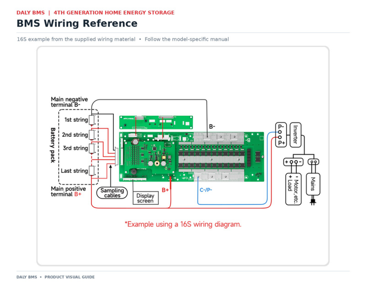
16S wiring example supplied for reference; not a substitute for the model-specific manual.
Battery sampling harness: follow the approved sequence
The supplied overview depicts a sampling harness connected across the series-cell measurement points, beginning at the battery pack’s negative end and progressing through the cell connections toward the positive end. It also describes checking the voltage between adjacent sampling leads. This is a critical verification task: the exact sequence, acceptable readings and test method must come from the applicable DALY manual and the battery-pack design. Do not infer a safe pin order from an image alone.
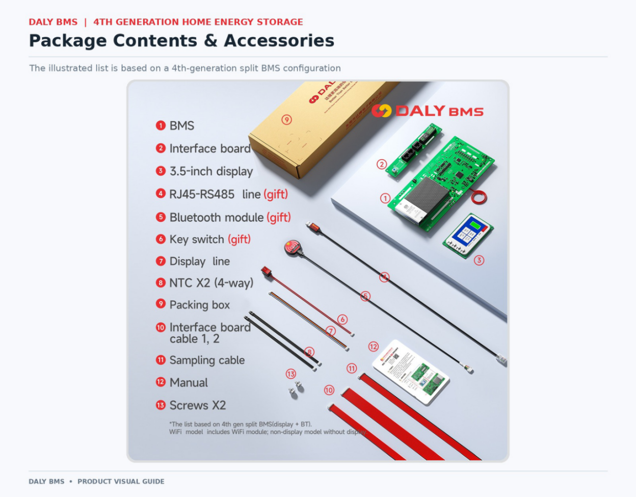
Sampling cable and accessory overview from the supplied product image.
Power connections and polarity checks
The reference material identifies the BMS negative connection and the pack’s main negative terminal, as well as the output and charge/discharge connection labels. Incorrect polarity, connection order or measurement practice can damage equipment and create a serious electrical hazard. For that reason, this article intentionally does not provide a universal step-by-step energising sequence. A qualified battery-system technician must follow the model-specific instructions, isolate the system as required and verify each connection using the approved procedure.
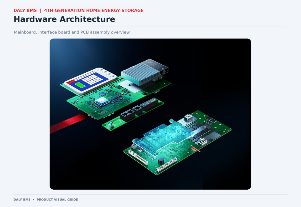
BMS mainboard and interface-board assembly.
Display, temperature sensor and communication leads
The supplied product comparison lists an NTC cable length of 650 mm and identifies UART communication on the mainboard and CAN plus RS485 on the interface board. The product images also show a display connection. Confirm which sensors, cables, ports and accessories are included with the ordered model, and use only the specified pinout and cable assembly. Never assume that connectors that look similar have the same electrical assignment.
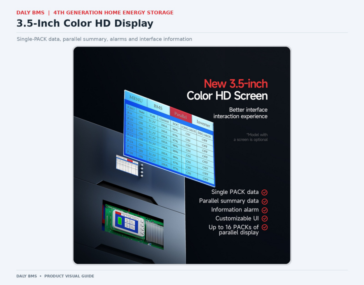
Display interface shown in the supplied product materials.
Pre-commissioning review
Before the system is energised, the installer should verify the BMS model and cell count, battery chemistry, terminal polarity, sampling harness order, connector seating, insulation, cable routing, protective devices and inverter interface against the approved design. If a label, measured value or connector position does not match the manual, stop and resolve the discrepancy. Commissioning should be performed by personnel qualified for the battery system and its electrical hazards.
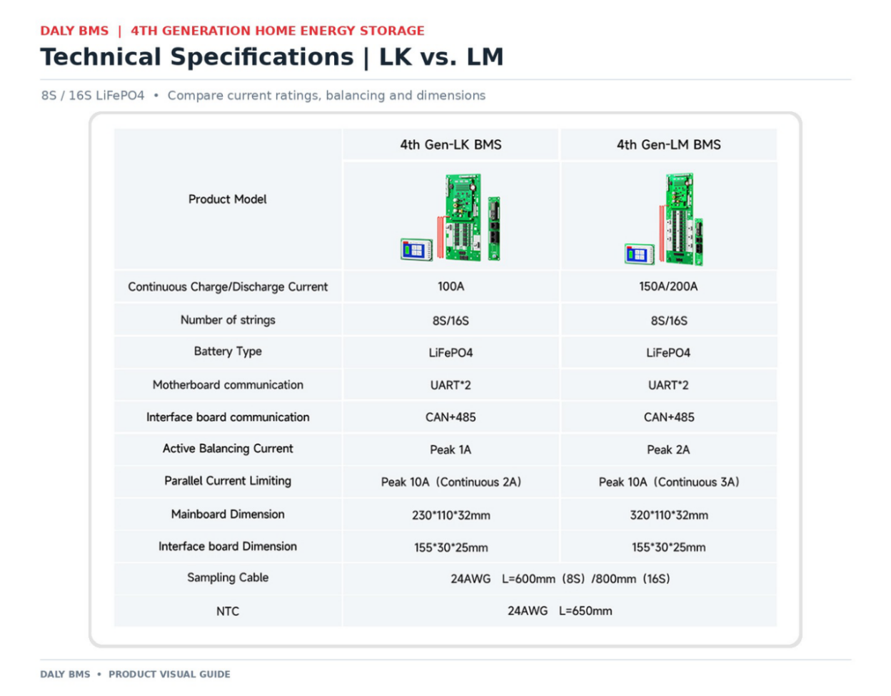
Check the model and specification before installation.
Conclusion
The supplied 16S diagram is useful as a visual reference for identifying major BMS connections. It is not sufficient on its own to install or commission a battery system. Use the current manual for the exact DALY model and board revision, and have a qualified technician verify the sampling sequence, polarity and power connections before operation.
Technical References
Product-specific statements should be checked against the current documentation for the exact model and configuration. The following DALY resources provide product-family and specification context:
· DALY 4th Generation LK and LM BMS product information — https://www.dalybms.com/news/home-energy-storage-bms/
· DALY Home Storage BMS product family — https://www.dalybms.com/home-storage-bms/
· DALY 16S wiring example and product documentation — https://www.dalybms.com/
Publication and Rights Notes
· The article text has been restructured and rewritten for clearer editorial expression. This is an editorial risk-reduction pass, not a plagiarism-database certificate or legal opinion.
· Image credit: DALY product materials supplied for this article. Confirm that DALY owns the rights or has a license permitting website/blog use, including any third-party photographer, designer, stock-image or agency rights.
· Confirm the latest SKU, hardware revision, firmware, options and datasheet before publication.
· Safety review: this article is an installation overview, not a wiring procedure. DALY engineering must approve terminal names, diagrams and safety wording for the exact board revision.
-
AuthorPosts

- You must be logged in to reply to this topic.